Electronics Basics: Components and Your First Circuit
Your First LED Circuit
In this lesson you will
- Calculate the series resistor for an LED
- Build and test an LED circuit on a breadboard
- Troubleshoot an LED that does not light
Introduction
Time to put everything together. You will work out the right resistor for an LED, then build the circuit. This is the "hello world" of electronics.
The problem
An LED lets almost any current through once it is on, so it needs a resistor in series to limit it. Too much current and the LED burns out. The resistor value comes from Ohm's law.
The calculation
Typical values for a small red or yellow LED (check your LED's datasheet):
- Forward voltage: about 2 V. This is the voltage the LED drops when it is on.
- Current: about 20 mA (0.02 A) at most, and 10 mA is often bright enough.
With a 5 V supply, the resistor must drop the rest:
Voltage across the resistor = 5 V − 2 V = 3 V
R = V ÷ I = 3 ÷ 0.02 = 150 Ω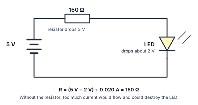 The LED circuit. The resistor takes up the voltage the LED does not.
Check the resistor's power: P = I² × R = 0.02 × 0.02 × 150 = 0.06 W. That is well under a quarter-watt rating, so a normal 0.25 W resistor is fine.
If you do not have 150 Ω, use the next standard value up, such as 220 Ω. The LED will be a little dimmer and safer: I = 3 ÷ 220 = 13.6 mA.
Quick quiz
You use a 5 V supply and an LED that drops 2 V. What resistor gives about 10 mA?
Build it
You need: a breadboard, a 5 V source (for example a USB power supply module, or three 1.5 V AA batteries in series, giving 4.5 V), a resistor of about 150 to 330 Ω, an LED, and two wires. With 4.5 V, a 220 Ω resistor works well.
- Power off. Connect the source to the breadboard's power rails last.
- Put the LED in the board with its long leg (anode, +) in one column and short leg (cathode, −) in a different column.
- Connect one leg of the resistor to the same column as the long leg. Put the other end of the resistor in the + rail.
- Connect a wire from the column of the short leg to the − rail.
- Connect the power. The LED should light.
Remember: the resistor can go on either side of the LED, because it is in series.
If it does not light
- LED backwards? Turn it around. A short time backwards at these low voltages is usually harmless, but do not leave it that way.
- Loose connection? Check each leg sits properly in its column.
- Wrong rail? Check + and − rails, and that the rail is not split in the middle.
- Flat battery? Measure its voltage with the multimeter.
- Wrong holes? Both legs of the LED in the same column means no light, because they are shorted.
- Resistor too large? A resistor of tens of kΩ gives a barely visible glow.
Stay safe
Use low voltage only. If anything gets hot, disconnect the power. Never connect an LED directly to a battery with no resistor.
Going further
- Add a switch in series, to turn the LED on and off.
- Put two LEDs in series, using the voltage drop of each, or in parallel with one resistor for each.
- Use a free online circuit simulator to try ideas with no risk.
- Try a microcontroller board next, which lets you control LEDs with code.
Try it yourself
Calculate the resistor for a 9 V supply with an LED at 15 mA and a 2 V drop. Check the power in the resistor, and choose the nearest standard value. Answer: 7 ÷ 0.015 is about 467 Ω, so 470 Ω, with about 0.1 W.
Summary
- An LED needs a series resistor, calculated as (supply voltage − LED voltage) ÷ current.
- Build it on a breadboard with the long LED leg towards positive, and the resistor in series.
- If it does not light, check polarity, connections, rails and the battery.
Lesson complete
+20 XP
Nice work. Keep going while it is fresh.