Electronics Intermediate: Power, Transistors, Op-Amps and Logic
Diodes and DC Power Supplies
In this lesson you will
- Explain how a bridge rectifier works
- Estimate ripple voltage for a smoothing capacitor
- Describe the stages of a basic DC power supply
Introduction
Almost every electronic device needs steady DC, but it is often powered from AC. A power supply does the conversion, in stages: step down, rectify, smooth and regulate. This lesson explains the middle two stages, which rely on diodes and a capacitor. The mains side of a power supply is dangerous. Study it, but only build from low-voltage, approved transformers or adaptors.
Diode behaviour in practice
A silicon diode conducts current in one direction only, once the voltage across it exceeds about 0.7 V (the forward voltage drop). In the other direction it blocks, up to its reverse voltage rating. Always choose a diode with a current and reverse voltage rating well above what the circuit needs.
Half-wave and full-wave rectification
A single diode in series with the load passes only the positive halves of an AC wave. This is half-wave rectification, and it wastes half the power.
A bridge rectifier uses four diodes to use both halves:
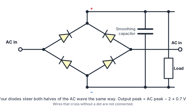 A bridge rectifier with a smoothing capacitor. Two diodes conduct on each half-cycle.
- When the top AC terminal is positive, current flows through two diodes, through the load, and back.
- When the polarity swaps, the other pair conducts, and current still flows through the load in the same direction.
The output pulses at twice the input frequency: 100 Hz from 50 Hz mains, or 120 Hz from 60 Hz. Two diodes are in the path each time, so the output peak is lower than the AC peak by about 2 × 0.7 = 1.4 V.
Quick quiz
Why does a bridge rectifier give an output that pulses at twice the AC frequency?
Smoothing with a capacitor
The pulses fall to zero between peaks. A reservoir (smoothing) capacitor charges to the peak, then supplies the load while the voltage dips. The remaining wobble is ripple.
An estimate for a full-wave rectifier:
Ripple ≈ I ÷ (2 × f × C)where I is the load current in amps, f is the mains frequency in hertz and C is in farads.
Example: a 100 mA load, 50 Hz mains and a 1000 µF capacitor:
Ripple ≈ 0.1 ÷ (2 × 50 × 0.001) = 1 VDoubling the capacitance halves the ripple, and a bigger load increases it. Check the capacitor's voltage rating with margin, and its polarity, since electrolytic capacitors can burst if connected backwards.
Regulating
Ripple and voltage changes remain. A voltage regulator after the capacitor gives a steady output, such as 5 V, and removes most ripple. The input must stay above the regulator's required minimum (the dropout voltage) even at the bottom of the ripple.
The stages together
- Transformer (or adaptor): steps AC down and isolates it
- Rectifier: AC to pulsing DC
- Smoothing capacitor: reduces ripple
- Regulator: steady output
- Protection: a fuse on the input, and perhaps a reverse-polarity diode or output protection
Other diode uses
- Reverse-polarity protection: a series diode blocks a battery connected backwards, at the cost of 0.7 V.
- Flyback diodes across relay and motor coils.
- Zener diodes hold a fixed voltage in reverse, as simple references or protection.
- LEDs are diodes that emit light, and need a current-limiting resistor.
Try it yourself
A supply must deliver 200 mA from a 12 V AC secondary at 50 Hz, with no more than 0.5 V ripple. Estimate the capacitor size needed using the formula (about 4000 µF, so a 4700 µF capacitor), and the approximate peak DC voltage (12 × 1.414 − 1.4 ≈ 15.6 V).
Summary
- Diodes conduct one way, with about 0.7 V forward drop, and a bridge of four uses both halves of the AC.
- A smoothing capacitor reduces ripple, estimated by I ÷ (2 × f × C), and a regulator gives a steady output.
- Work only from low-voltage sources, and check voltage and polarity ratings of capacitors and diodes.
Lesson complete
+20 XP
Nice work. Keep going while it is fresh.
Sources and further reading