Electronics Intermediate: Power, Transistors, Op-Amps and Logic
Op-Amps and Analogue Signals
In this lesson you will
- Describe an ideal op-amp and the effect of negative feedback
- Calculate the gain of inverting and non-inverting amplifiers
- Explain buffers and comparators and the practical limits of real op-amps
Introduction
The operational amplifier, or op-amp, is a small chip that amplifies the difference between two input voltages. With a few resistors, it becomes an amplifier, filter, buffer, sensor interface or comparator. It is one of the most useful building blocks in analogue electronics.
Inputs, output and gain
An op-amp has:
- A non-inverting input (+)
- An inverting input (−)
- One output
- Power connections (a supply, sometimes both positive and negative)
It outputs a voltage equal to its enormous open-loop gain (tens of thousands or more) times the difference (V+ − V−). Used without feedback, the output slams to one supply rail or the other, which makes a comparator. For amplifiers, you add negative feedback.
Negative feedback: the key idea
Connect part of the output back to the inverting input. The op-amp then adjusts its output until the two inputs are almost equal. For an ideal op-amp with negative feedback, two helpful rules hold:
- The two inputs are at the same voltage (V+ = V−).
- The inputs draw no current.
These rules let you solve most op-amp circuits with Ohm's law.
Non-inverting amplifier
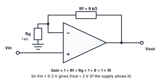 A non-inverting amplifier. The two resistors form a divider that feeds back to the inverting input.
The feedback resistors Rf and Rg form a voltage divider on the output. The op-amp makes that divider's midpoint equal to Vin, so:
Gain = 1 + Rf ÷ Rg = 1 + 9 ÷ 1 = 10An input of 0.2 V gives 2 V at the output. The output has the same polarity as the input. The minimum gain is 1.
Quick quiz
A non-inverting amplifier has Rf = 20 kΩ and Rg = 5 kΩ. What is its gain?
Inverting amplifier
The input goes through a resistor Rin to the inverting input, with the feedback resistor Rf from output to that input, and the non-inverting input grounded:
Gain = − Rf ÷ RinThe minus sign means the output is flipped (inverted). With Rf = 100 kΩ and Rin = 10 kΩ, the gain is −10. The input resistance of the circuit is Rin, which matters when connecting sensors.
Voltage follower (buffer)
Connect the output directly to the inverting input, and the signal to the non-inverting input. The gain is exactly 1. It looks pointless, but it has a high input resistance and a low output resistance, so it lets a weak source, such as a sensor or a voltage divider, drive a load without being loaded down.
Comparator
Without feedback, an op-amp (or a dedicated comparator chip) compares two voltages: if V+ > V−, the output goes high, otherwise low. Examples: a light-activated switch, a threshold alarm or turning an analogue signal into a digital one. Adding hysteresis with positive feedback prevents chatter when the signal hovers near the threshold.
Real-world limits
- Supply rails: the output cannot exceed the supply. A gain of 10 on a 1 V input from a 5 V supply is not possible. Choose a rail-to-rail op-amp for low supplies.
- Input range and offset: inputs must stay within allowed limits, and small offset voltages shift the output.
- Bandwidth: gain falls at high frequency. The gain-bandwidth product is roughly constant, so a gain of 100 has much less bandwidth than a gain of 1.
- Output current: op-amps drive only modest loads. Use a transistor or driver stage for more.
- Noise and stability: layout and decoupling matter. Place a 100 nF capacitor close to the supply pins.
- Read the datasheet.
Single supply operation
With a single supply, such as 5 V and ground, signals that swing below ground cannot be handled directly. A common solution is to bias the signal to mid-supply with a voltage divider, and use capacitors to block the DC.
Try it yourself
Design an inverting amplifier with a gain of −5 using resistors from the E12 series: for example Rin = 10 kΩ and Rf = 47 kΩ gives −4.7, which is close. Calculate the output for a 0.3 V input.
Summary
- An op-amp amplifies the difference between its inputs, and negative feedback makes the inputs equal.
- Non-inverting gain is 1 + Rf ÷ Rg, and inverting gain is −Rf ÷ Rin. A follower has gain 1 and buffers a signal.
- Respect supply rails, bandwidth, output current and datasheet limits.
Lesson complete
+20 XP
Nice work. Keep going while it is fresh.
Sources and further reading