Electronics Basics: Components and Your First Circuit
Breadboard and Multimeter
In this lesson you will
- Explain how a breadboard is connected inside
- Measure voltage, resistance and continuity with a multimeter
- Avoid the common multimeter mistakes
Introduction
Two tools turn electronics from theory into hands-on fun: a breadboard for building circuits without soldering, and a multimeter for measuring them. Both are cheap and used by professionals.
The breadboard
A breadboard is a plastic board full of small holes. Metal strips hidden underneath connect certain holes together. You push part legs and wires into the holes. No solder is needed, and you can change the circuit easily.
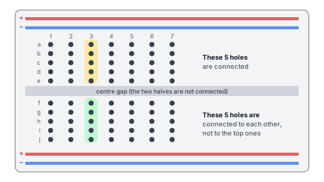 Inside a breadboard. The five holes in a column (a to e) are connected, the five below the gap (f to j) are connected, but the two halves are separate.
How it is connected:
- Columns: in the middle area, each numbered column is connected in two groups: holes a to e, and holes f to j. The centre gap separates the halves, so chips can straddle it without shorting.
- Power rails: the long lines along the sides, marked + and −, are connected along their full length. Use them for the battery connections. (On some larger boards the rails are split in the middle, so check yours.)
Tips:
- To connect two parts, put their legs in the same column, on the same side of the gap.
- Use short wires and keep neat. Messy wiring makes mistakes hard to find.
- Breadboards are for low voltage only, and are not for mains.
Quick quiz
Two resistor legs are pushed into holes b3 and d3 on a breadboard. Are they connected?
The multimeter
A multimeter measures several things. Learn four settings:
- DC voltage (V with a straight line): measure voltage across a part or battery. Connect the probes in parallel, across the thing you measure. Red probe to the more positive point.
- Resistance (Ω): measure a resistor's value. Power must be off, and the part should be out of the circuit or disconnected on one side.
- Continuity (a sound or diode symbol): beeps when there is a low-resistance path. Useful for checking wires and connections. Power must be off.
- Current (A or mA): measure how much current flows. The meter must be placed in series, breaking the circuit and connecting through the meter. This is the setting people most often misuse.
Mistakes to avoid
- Do not measure current by connecting probes straight across a battery on the current setting. That is a short circuit and can blow the meter's fuse or worse.
- Move the red lead back to the voltage socket after measuring current.
- Never measure resistance on a powered circuit.
- Start on a higher range if your meter is not automatic, then reduce it.
- Do not use a beginner multimeter on mains. Check the meter's safety rating and training before going anywhere near mains, or leave it to professionals.
Try it yourself
Measure the voltage of a new AA battery on the DC voltage setting. It should read about 1.5 V. Then measure the resistance of a resistor and compare it with the colour code.
Summary
- A breadboard joins holes in columns of five, with power rails along the sides, and needs no solder.
- A multimeter measures DC voltage (in parallel), resistance (power off), continuity and current (in series).
- Never measure current across a battery, and never measure resistance on a live circuit.
Lesson complete
+20 XP
Nice work. Keep going while it is fresh.
Sources and further reading